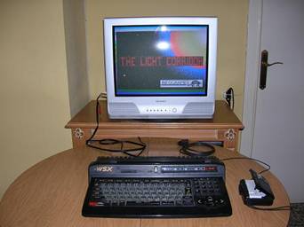
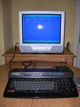
Cassette port in Panasonic A1-WSX

First of all i want to say that I have not discovered this. I Rather re-discovered it, if it can be named so.
As you will see later on it appeared in an article of the japanese MSX Magazine, though i descovered it by my own.
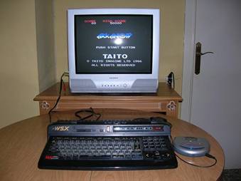
Well, some time ago I had a TurboR A1-ST and then a GT. None of them admited the loading command through the cassette port, i.e., run”cas:”, bload”cas:” o cload.
They always promted an error message.
The day came when I sold my TurboR and later on a friend gave me his A1-WSX. And how was my surprise when i saw it did accept the cassette commands with no error messages prompted. In fact it always got stuck for a while doing nothing (no cursor and so), i.e., saving the program i typed.
The question was on how could I connect a walkman to my MSX.
I asked all around in the forums and someone told me the model before mine, the A1-WX, did have a cassette port.
I asked if someone could open the computer and take some pictures of the motherboard in order to, somehow,
compare them and put in its place what may be missing. I didn't get any answer.
I asked if someone had the technical schemes from those computers. Someone told me they existed, obviously, but the thing didn't go any further.
Some time later mesiasmsx posted a scheme he claimed came in a japanese MSX Magazine.
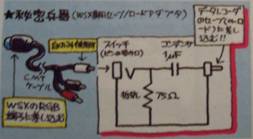
I let it be for a while, for it seemed a little bit absurd to me that it could load/save through the RGB port.
Furthermore, putting a circuit in between with no explanation at all seemed a little nonsense.
I asked again in the forums and to mesiasmsx if it could be possible to scan the whole article from the magazine and not just the circuit.
Mi japanese is quite bad, but i might be able to make clear something out of it. I didn't get any answer.
This way came the day when i thought about something.
Knowing the computer got stuck when I typed save"cas:" (so it was really saving, on the air) to come back to its former status
after a while, I remembered the interferences my SONY HB-20P used to produce in the short wave a long time ago (funny experiments one used to make...).
So, i prepared my A1-WSX to be saving for a longer time while i searched through the short wave dial until i found it and it happened.
Here
can you listen to what i registered with my radio.
I asked again in the forums, giving a link to this mp3, to see if someone would answer, but nothing.
I opened the A1-WSX and searched all around the motherboard looking for any connection that would emit sound while saving a program.
Someone in the forums told me to look for it in the PPI.
The fact is that I finally found sound in the RGB connector, which came in the upper scheme.
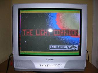
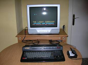
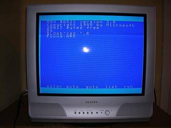
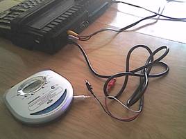
I bought a DIN connector and solded a 1.5mm jack to connect it to my walkman. I started loading “THE LIGHT CORRIDOR” and
it loaded!!! I flipped out.
It was just before my eyes. After so much searching it was in the RGB connector. I started checking
a lot of games and all of them worked.
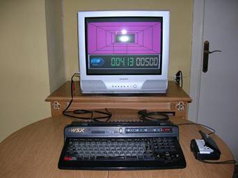
There's no problem in this . The problem comes when saving data.
The signal comes with some noise, though it is also true that the electrical connections in my appartment don't have a good
ground connection and it can provoque the noise i mention. But it does save data.
Here
you have a saving sample.
Once i got games working i wondered what for was it necessary to use the famous circuit from the upper scheme.
I analyzed it and reproduced it with no problems.
I didn't notice any special difference once i putted it in its place. The only thing is that it attenuates the signal a little bit, i.e., it sounds more quiet.
You can check it with these two audio files. One
doesn't have the circuit connected and the other
does.
This way this connector is not that much necessary.
Just making the connection cable from the RGB to the walkman is more than enough.
Solutions
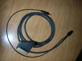
If we normally work with the A/V cables (RCA) we can use without any problem a standard MSX
cassette connector (at least my HB-20P's works perfectly).
The white connector, that goes directly to nr 5 pin (data) will be used both to load and save data.
The other two (red and black in my case) won't be used at all. People from Panasonic managed to remove the MOTOR ON/OFF relé,
so we will must pay attention to stop the walkman when necessary.
With this easy solution we avoid any mess solding and so.
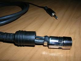
The other solution, a little more complicated due to need of solding but, under my point of view, more curious and in just one cable, is
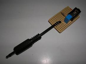
to incorporate a cable with a 1.5mm jack to the RGB original cable.
To do so, we'll need a 1.5mm jack male connector and a cable with two wires the length we may need, solder and lead.
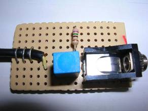
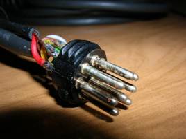
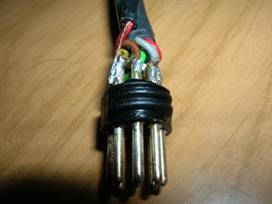
We unscrew the plastic armor from the DIN connector.
Next, we separate the metal side armors.
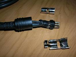
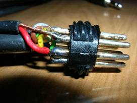
In my connector I putted insulating tape because when we'll put the extra cable, it'll be a little difficult to close
everything and it's possible to break some part of it. So it's better if it's protected.
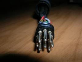
This is the connector from the front side.
The numbers mark the pins we're gonna connect (5 and 3).
In pin nr 5 is the +5V connection, according to msxnet.
In this pin we have already a wire connected. Thus I decided to sold the ground (wire with no plastic cover) through the outside.
Solding them together inside the same pin, would have meant a great mess. This way we avoid it.
Since pin nr3 is not in use, there's no problem on putting our data wire (the one with a plastic cover) and sold it.
Once done this we mount back the connector with the metal and plastic covers.
It'll take us a little bit since the cable will fit very tight inside the plastic cover, but we'll finally get it. And ready!
My explanation may not be too much clear and I may have missed some step or forgot to mention someone (more than probable).
In that case, don't hesitate to
write me
in order to modify it.
C u!